Software Redevelopment Report
The source code and design for the software on the Indus box is not available, so it needs to be reverse engineered and re-engineered. This process included reverse engineering siginificant parts of the circuit design. This results of this exercise are described in this report.
Product Overview
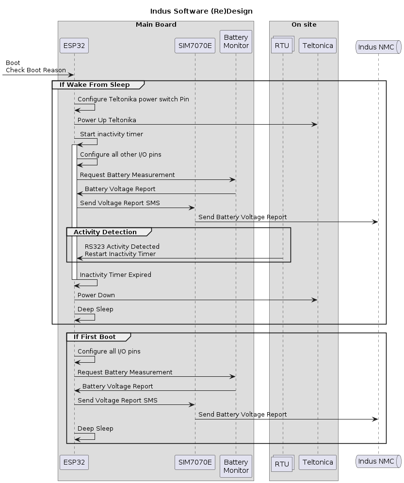
A bespoke PCB contains and ESP32 micro-controller connected to a lower power cellular module, the SIMCOM SIM7070E. This modem has a very low standby power, so can remain on permanently. This ESP32 board has inputs connected to a battery monitor and RS-232 sensing to be connected to the customer device. The ESP32 is put into deep-sleep mode most of the time, only been awoken when either an SMS arrives on the SIM7070E or the external device sends data over the RS232.
When the ESP32 is awoken from deep-sleep it turns on the Teltonika modem which is configrued to conect to the customer network via AWS. After a configured length of time or no activity on the RS-232, the modem is turned off and the ESP32 is put back into deep-sleep. The ESP32 when awoken will measure the battery voltage and send it to AWS. This will allow the customer to detect when the battery is low and in need of charging.
Reverse Engineering
The first step was to reverse engineer the PCB. The PCB is a 4 layer design, so pure inspection was insufficient to reverse engineer it. The PCB production files (Gerber files) were used to understand the circuti design. The inner layers contain only 5 connections on one layer and none on the other.
The programming/ monitoring port is a 3.3V serial connection, connecting to this port (using a USB to serial adapter) gives access to the boorloader and some debug info. An example log of the current software is shown in Appendix A.
An attempt was made to extract and decompile the software already on the ESP32. This was not successful as the code did not contain the ‘debugging symbols’, so the decompiled code was nonsense; an example can be seen in Appendix B.
Signals Which Wake The Board From Deep Sleep
The ESP32-WROOM-32UE has multiple pins which will wake the micro-controller from deep sleep. The hardware design ensures that these several inputs are connected via these inputs, therefore allowing the ESP32 to spend most of the opearating life in deep sleep.
| Pin\n Number | Source | Notes |
|---|---|---|
| 34 | SIM7070E Ring Indicator | Awake board when SMS received |
| 35 | RS-232 TX Line | Awake board when RTU attempts to send to Teltonika modem |
Logic Levels
The ESP32 runs on 3.3V logic; there SIM7070E uses 1.8V logic. The cuircuit design uses 4 transistors as logic level converters.
New Software Design
There is a copy of the new code in Appendix C.
Board Connections
| Device | Pin | Name | Name | Pin | Device | Notes |
|---|---|---|---|---|---|---|
| ESP32 | 10 | IO25 | TXD | 9 | SIM7070E | Modem to ESP, via Q7 |
| ESP32 | 11 | IO26 | RXD | 10 | SIM7070E | ESP to Modem, via Q8 |
| ESP32 | 6 | IO34 | RI | 4 | SIM7070E | Modem to ESP, SMS notification |
| ESP32 | 26 | IO4 | DTR | 3 | SIM7070E | ESP to Modem, via Q5 |
| ESP32 | 12 | IO27 | PWRKEY | 1 | SIM7070E | |
| n/a | n/a | n/a | PWRON | 6 | SIM7070E | connected to VD_EXT of SIM7070 |
| ESP32 | IO35 | 7 | n/a | RS232-TX | External | detect when to power-on modem |
| ESP32 | IO2 | 24 | n/a | n/a | LED | On board LED |
| ESP32 | 36 | IO22 | SCL | 4 | IN219A | I2C bus |
| ESP32 | 33 | IO21 | SDA | 3 | IN219A | I2C bus |
Python - Connect to SIM7070E
Modem to ESP32 connection uses
from machine import Pin, UART
from time import sleep

pwrkey = Pin(27, Pin.OUT, value=1)
dtr = Pin(4, Pin.OUT, value=1)
tx = Pin(26, Pin.OUT)
rx = Pin(25, Pin.IN)
uart = UART(1, tx=tx, rx=rx, baudrate=57600, timeout=50)
pwrkey.value(0)
sleep(2)
pwrkey.value(1)
sleep(2)
l = uart.read()
if l:
    print(l)

uart.write("\n\nAT\n\n")
for _ in range(5):
    l = uart.read()
    if l: print(l)
Python - Connect to Teltonika Modem
ext = Pin(17, Pin.OUT, value=0)
# to turn Teltonika modem on, set value to 1
ext.value(1)

# to turn Teltonika modem on, set value to 1
ext.value(0)
Python - Connect to On-Board LED
led = Pin(2, Pin.OUT, value=0)
led.value(1)
led.value(0)
Python - Connect to Battery Monitor
IN219A - using Micropython library from https://github.com/chrisb2/pyb_ina219 (license MIT)
from machine import Pin, UART, SoftI2C
from ina219 import INA219
import time

i2c = SoftI2C(freq=100000, scl=Pin(22, Pin.OUT), sda=Pin(21, Pin.OUT))
i2c.scan()
# response is [64]

ina = INA219(0.1, i2c)
# 0.1 is shunt resistance
print(ina.voltage())
Python - Connect to RTU
This connection is input only, to detect RS-232 traffic, then either turn on the Teltonika Modem or restart the in-activity timer.
from machine import Pin
import time

txactivity = Pin(35, Pin.IN)
if txactivity.value() == 1:
    if ext.value() == 0:
        ext.value(1)
    restarttimer()
Board Design Issues
Battery Connectors and Protection
The battery connections are spade terminals, with identical connections for positive and negative. Hence it is possible to reverse the connections to the battery. If this occurs, the on-board fuse is specified as a slow blow fuse, so damage to circuit is possible. During reverse engineering, this occured DEstroying the SIM7070E and blowing the fuse.
The fuse is a non-resetable surface-mount device, which can only be replaced with modern soldering equipment (hot air or skilled use of soldering iron and solder wick/ vacuum pump).
I suspect a protection diode has not been used beacuse of the power loss (approx 5%, i.e. 0.6V out of 12V).
I would suggest using a polarised connector, such as T plug or XT30, to reduce the likelihood of mistakes.
Code Installation
The new code is written in a version of Python desigend so embedded devices, called Micropython. So Micropython must be installed onto the board before the software can be copied onto the board. Both can be acheived from within the Thonny Python editor.
The installation process is:
- Install Thonny,
- Connect to the board,
- Install Micropython onto the board,
- copy the software onto the board.
Install Thonny
Thonny is a code editor designed to work with Python and Micropython. It is available for Windows, Linux and Mac.
Installing Thonny is easy following the Instructions on the Thonny website. On Windows, it just requires downloading the executable installer.
Connect to the board
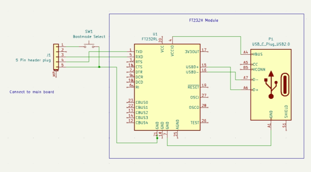
The board must be connected to the computer via a USB to serial adapter. Simon can provide an adapter, which includes an additional bootmode switch to enable booting into bootloader mode. The cable is only required for programming the board and is not required for normal operation of the board.
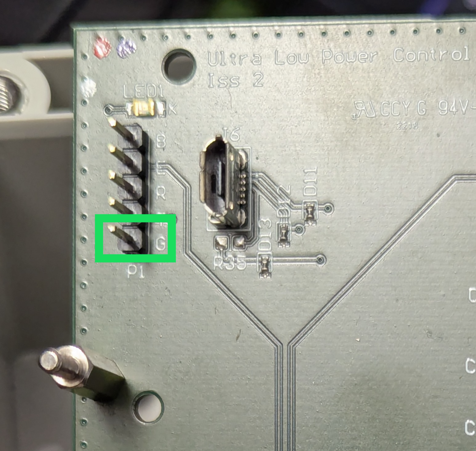
- Connect the cable to the 5 pin header BEWARE This connector must be connected the right way around, but can be inserted either way. The Ground pin is clearly marked on the plug and marked with an G (for Ground) on the pin header - see photo below.
- While pressing the boot switch, turn on the power to the board. Again BEWARE when connecting the power. The 2 spade connectors can be swapped, which will blow the on-board fuse, resulting in needing to send the unit back for repair. Hold the boot switch for 3 seconds after powering up the board.
Install Micropython onto the board
This only needs to be done once per board. It is not required to be installed every time the board is powered up.
- Open Thonny app.
- Connect the board to the computer via USB. If the Shell window, shows something like
MPY: soft reboot
MicroPython v1.24.0 on 2024-10-25; Generic ESP32 module with ESP32
Type "help()" for more information.
>>>
then Micropython is already installed and you can skip to the next step.
- Select Run -> Configure Interpreter
- Click Install or update MicroPython
- Select the correct USB port for the FT232 cable
- Select ESP32, Espressif ESP32 / WROOM, then click Install.

The process will take around 2 minutes. After it completes, power-cycle the board and the Shell window should show Micropython message as shown above.
Copy the software onto the board
- Select File -> Open,
- Select This Computer,
- Navigate to the folder containing the software files.
- Select the file cogent-esp32-firmware.py.
- Select File -> Save as and save it in the same folder.
- Select MicroPython device,
- Type the filename boot.py into the box, then click OK.
Appendix A
Old software boot log.
rst:0x1 (POWERON_RESET),boot:0x17 (SPI_FAST_FLASH_BOOT)
configsip: 0, SPIWP:0xee
clk_drv:0x00,q_drv:0x00,d_drv:0x00,cs0_drv:0x00,hd_drv:0x00,wp_drv:0x00
mode:DIO, clock div:2
load:0x3fff0030,len:6612
load:0x40078000,len:13692
load:0x40080400,len:3724
entry 0x4008068c
I (27) boot: ESP-IDF v4.4-dirty 2nd stage bootloader
I (27) boot: compile time 09:02:26
I (27) boot: chip revision: 3
I (30) boot_comm: chip revision: 3, min. bootloader chip revision: 0
I (38) boot.esp32: SPI Speed      : 40MHz
I (42) boot.esp32: SPI Mode       : DIO
I (47) boot.esp32: SPI Flash Size : 4MB
I (51) boot: Enabling RNG early entropy source...
I (57) boot: Partition Table:
I (60) boot: ## Label            Usage          Type ST Offset   Length
I (68) boot:  0 nvs              WiFi data        01 02 00009000 00006000
I (75) boot:  1 phy_init         RF data          01 01 0000f000 00001000
I (82) boot:  2 factory          factory app      00 00 00010000 00100000
I (90) boot: End of partition table
I (94) boot_comm: chip revision: 3, min. application chip revision: 0
I (101) esp_image: segment 0: paddr=00010020 vaddr=3f400020 size=0f0e8h ( 61672) map
I (132) esp_image: segment 1: paddr=0001f110 vaddr=3ffb0000 size=00f08h (  3848) load
I (134) esp_image: segment 2: paddr=00020020 vaddr=400d0020 size=36674h (222836) map
I (219) esp_image: segment 3: paddr=0005669c vaddr=3ffb0f08 size=01624h (  5668) load
I (221) esp_image: segment 4: paddr=00057cc8 vaddr=40080000 size=0e078h ( 57464) load
I (248) esp_image: segment 5: paddr=00065d48 vaddr=400c0000 size=00064h (   100) load
I (248) esp_image: segment 6: paddr=00065db4 vaddr=50000000 size=00014h (    20) load
I (261) boot: Loaded app from partition at offset 0x10000
I (261) boot: Disabling RNG early entropy source...
I (277) cpu_start: Pro cpu up.
I (277) cpu_start: Starting app cpu, entry point is 0x40081420
I (0) cpu_start: App cpu up.
I (291) cpu_start: Pro cpu start user code
I (291) cpu_start: cpu freq: 160000000
I (291) cpu_start: Application information:
I (295) cpu_start: Project name:     blink
I (300) cpu_start: App version:      1
I (305) cpu_start: Compile time:     Jul  4 2022 09:02:35
I (311) cpu_start: ELF file SHA256:  ecd2efa0bc491eeb...
I (317) cpu_start: ESP-IDF:          v4.4-dirty
I (322) heap_init: Initializing. RAM available for dynamic allocation:
I (329) heap_init: At 3FFAE6E0 len 00001920 (6 KiB): DRAM
I (335) heap_init: At 3FFB4098 len 0002BF68 (175 KiB): DRAM
I (341) heap_init: At 3FFE0440 len 00003AE0 (14 KiB): D/IRAM
I (348) heap_init: At 3FFE4350 len 0001BCB0 (111 KiB): D/IRAM
I (354) heap_init: At 4008E078 len 00011F88 (71 KiB): IRAM
I (362) spi_flash: detected chip: generic
I (365) spi_flash: flash io: dio
I (371) cpu_start: Starting scheduler on PRO CPU.
I (0) cpu_start: Starting scheduler on APP CPU.
II (10) uart: queue free spaces: 20

************************************************************************************************************

ESP32 with GSM SIM7070 - WLR Phase 2

This is build version: 1.09

************************************************************************************************************

Booted CPU Frequency is: 160
This is boot number: 1
Power saving CPU Frequency is: 80
**************************************************
******* Starting wakeup reason checks.

Who dares wake me from my slumber??? ;-)
This is boot number: 1
wake reason: 0
Wakeup was not caused by deep sleep. Cold start or reboot: 0

                                                            ******* End of wakeup reason checks.
**************************************************

Flash encrypted: 0
Firing up modem


**************************************************
******* Starting Voltage checks.

11.37
**************************************************
******* Starting GSM wakeup checks.

Initializing GSM....(May take more than 10 seconds)
Appendix B
Example decompiled code.
undefined4 FUN_00011df4(void)
{
  int iVar1;
  undefined4 uVar2;

  iVar1 = FUN_00011f9c(DAT_00010028,DAT_00010024);
  if (iVar1 == 0) {
    iVar1 = func_0xfffc84b8(1);
    *DAT_0001002c = iVar1;
    uVar2 = 0;
    if (iVar1 == 0) {
      FUN_00011fe4(*DAT_00010028);
      uVar2 = 0x101;
    }
  }
  else {
    uVar2 = 0x101;
  }
  return uVar2;
}

int FUN_00011e2c(int **param_1,int *param_2)
{
  int iVar1;
  int *piVar2;

  if (param_1 == (int **)0x0) {
    return 0x16;
  }
  if (param_2 == (int *)0x0) {
    iVar1 = 0;
  }
  else {
    if (*param_2 == 0) {
      return 0x16;
    }
    iVar1 = FUN_00044e10(param_2);
    if (iVar1 != 0) {
      return iVar1;
    }
    iVar1 = param_2[1];
  }
  piVar2 = (int *)func_0xfffcce74(8);
  if (piVar2 == (int *)0x0) {
    iVar1 = 0xc;
  }
  else {
    piVar2[1] = iVar1;
    if (iVar1 == 1) {
      iVar1 = func_0xfffc84b8(4);
      *piVar2 = iVar1;
    }
    else {
      iVar1 = func_0xfffc84b8(1);
      *piVar2 = iVar1;
    }
    if (*piVar2 == 0) {
      func_0xfffcce94(piVar2);
      iVar1 = 0xb;
    }
    else {
      *param_1 = piVar2;
      iVar1 = 0;
    }
  }
  return iVar1;
}

undefined4 FUN_00011e94(int *param_1)
{
  undefined4 uVar1;

  if (*param_1 == -1) {
    func_0xfffca7a0(DAT_00010030,0xffffffff);
    if (*param_1 == -1) {
      uVar1 = FUN_00011e2c(param_1,0);
    }
    else {
      uVar1 = 0;
    }
    func_0xfffca8a8(DAT_00010030);
  }
  else {
    uVar1 = 0;
  }
  return uVar1;
}
Appendix C
from machine import Pin, UART, SoftI2C, reset_cause, deepsleep, unique_id
import esp32
from ina219 import INA219
import time, ubinascii

PHONE_NUMBER = "+7802669150" # Baz's test SIM number, replace with Indus Controller number
DEEPSLEEPHOURS = 6 # 6 hours

if machine.reset_cause() == machine.DEEPSLEEP_RESET:
    # conigure output as 1 to turn on Teltonika modem
    ext = Pin(17, Pin.OUT, value=1)
    inactTime = startInactivityTimer()

configureAllPins()
configureWakingPins()
if not configureModem():
    machine.reset()
getAndSendVoltageReport()
# deep sleep for maximum of configured time in seconds
deepsleep(1000 * 3600 * DEEPSLEEPHOURS)

def configureAllPins():
    # configure SIM7070E
    pwrkey = Pin(27, Pin.OUT, value=1)
    tx = Pin(26, Pin.OUT)
    rx = Pin(25, Pin.IN)
    ringInd = Pin(34, Pin.IN)
    uart = UART(1, tx=tx, rx=rx, baudrate=9600, timeout=50)
    pwrkey.value(0)
    sleep(2)
    pwrkey.value(1)
    sendATcommand("AT+CMGF=1")
    # Configure on board LED
    led = Pin(2, Pin.OUT, value=0)
    # Configure i2c link to battery monitor
    i2c = SoftI2C(freq=100000, scl=Pin(22, Pin.OUT), sda=Pin(21, Pin.OUT))
    txactivity = Pin(35, Pin.IN)
    ina = INA219(0.1, i2c)

def configureWakingPins():
    esp32.wake_on_ext1(pins= (ringInd, ext, level=esp32.WAKEUP_ANY_HIGH))

def configureModem():
    cmdsAndResps = getModemInitCmdsAndResps()
    for cmd, reqdResp in cmdsAndResps:
        for retries in range(3):
            resp = sendATcommand(cmd, reqdResp)
            if reqdResp == "" or reqdResp in resp.lower():
                continue
        else:
            print(f'Error sending {cmd} response: {resp}')
            return False
    return True

def getModemInitCmdsAndResps():
    return [
        ('AT', 'OK'),
        ('ATE0','OK'),
        ('AT+CVHU=0','OK'), # Configure Hangup mode
        ('ATI','OK'), # Get modem information
        ('AT+CPMS="SM","SM","SM"','OK'), # Store messages in SIM card memory
        ('AT+CSCLK=0','OK')  # Set clock source to internal oscillator
        ('AT+GSN',''), # Get IMEI number
        ('AT+CCID',''), # Get IMSI number
        ('AT+CNMP=13',''), # Set network operator to Teltonika
        ('AT+CBAND="ALL_MODE"',''), # Set band to all modes
        ('AT+CREG?', 'CREG')  # Get network registration status
    ]

def getAndSendVoltageReport():
    battVoltage = ina.voltage()
    boardId = machine.unique_id()
    boardName = f"{boardId[0]:02x}{boardId[1]:02x}{boardId[2]:02x}{boardId[3]:02x}"
    voltageReport = json.dumps({'board':boardId,'V':battVoltage})
    sendSMS(voltageReport)

def sendSMS(contents):
    cmd = f'AT+CMGS="{PHONE_NUMBER}"\r\n{contents}\x1A'  # AT command to send SMS with termination character (Ctrl+Z)
    uart.write(cmd)
    time.sleep(5)  # Wait for the modem to process the command
    response = uart.read()
    if response:
        print("Modem response:", response.decode('utf-8').strip())
    else:
        raise Exception("Failed to send SMS")
    print("SMS sent successfully")

def sendATcommand(cmd, timeout=5):
    uart.write(cmd + '\r\n')  # Send command with CR+LF
    time.sleep(timeout)       # Wait for the modem to respond
    response = uart.read()     # Read the response
    return response.decode('utf-8').strip()  # Decode and strip whitespace
Appendix D
Links to reference material for devices used.